Lab-study reconstruction (updated November 2026). I have not verified an original VPLS/VPWS lab file in my private notes, so the design below is an independent learning explanation inspired by my broader MPLS/GNS3 work—not a claim that I deployed this service at an employer.
Three similar names, three different jobs
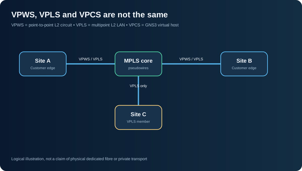
I kept mixing up VPWS, VPLS and VPCS. The easiest way to separate them is to ask: Are we emulating a customer Ethernet service, or just creating a test PC?
| Term | What it is | How I picture it |
|---|---|---|
| VPWS (Virtual Private Wire Service) | Point-to-point Layer 2 service typically built with pseudowires | One logical Ethernet wire between Site A and Site B |
| VPLS (Virtual Private LAN Service) | Multipoint Layer 2 VPN service | Multiple sites appear on one emulated Ethernet LAN |
| VPCS (Virtual PC Simulator) | Lightweight host used by GNS3 | A tiny PC for ip, ping and trace tests; not a VPN service |
VPWS: two sites and one logical circuit
Suppose two offices want to exchange Ethernet frames, and a provider transports them across an MPLS core. VPWS can give a point-to-point pseudowire service. The customer’s Layer 3 routing may run across the logical link if the circuit meets the requirements. It is logically like a wire, but it is not proof of dedicated physical fibre or permanently reserved bandwidth.
VPLS: more than two sites as one broadcast domain
VPLS makes several customer sites appear to share a Layer 2 LAN. Provider-edge devices learn customer MAC addresses and flood unknown, broadcast or multicast traffic according to service behaviour. The transport can involve MPLS pseudowires and a split-horizon rule across a full-mesh core; other VPLS designs use hierarchy. A large Layer 2 broadcast domain still needs careful loop prevention, capacity and failure planning.
I remember it this way: VPWS = wire; VPLS = LAN. Both are services; neither is an Internet “VPN app” in the usual end-user sense. The provider may isolate the forwarding domain without providing end-to-end encryption. If encryption is required, design it separately.
VPCS: my GNS3 end host
In GNS3, I use VPCS as a convenient endpoint so I can prove a routing or switching lab works. Example console:
PC1> ip 10.10.0.10/24 10.10.0.1
PC1> show ip
PC1> ping 10.20.0.10
PC1> trace 10.20.0.10
It is easy to use a VPCS node in the same lab as an MPLS network, but that does not make VPCS itself a Layer 2 VPN protocol.
My practical topology exercise
- Place customer edge CE-A and CE-B at either end of a provider core. Use VPCS nodes behind them.
- Validate reachability in the underlay with ordinary IP/OSPF first.
- For VPWS, build one point-to-point pseudowire using a capable MPLS L2VPN image.
- Extend to VPLS by adding CE-C and a third PE, then test MAC learning and broadcast reachability.
- Break a core path and observe what fails. A logical service depends on the underlay’s actual health.
Some GNS3 virtual-router images will not support the full L2VPN feature set. In that case keep the exercise conceptual, or use documented images that actually implement VPWS/VPLS.
What I learnt
The underlay decides how provider routers reach each other; the L2VPN service decides what Layer 2 connectivity the customer experiences. A test PC is only a test PC. Getting that vocabulary right prevents a lot of architecture confusion.
Shreyas Joshi
CCNA certified — Routing and Switching
References: RFC 4761 — BGP VPLS · RFC 4762 — LDP VPLS · RFC 4447 — Pseudowire setup · GNS3 VPCS documentation