
This article is all about building up linux platform driver. In this article, we will be writing a simple phy driver. In order to configure the phy driver, we will use Device tree overlay i.e. DTBO. Firstly, we need to enable the DTBO support in kernel. This can be done through menuconfig. If done properly, you should be able to see the following directory in the linux root file system.
#/sys/kernel/config/device-tree/overlays/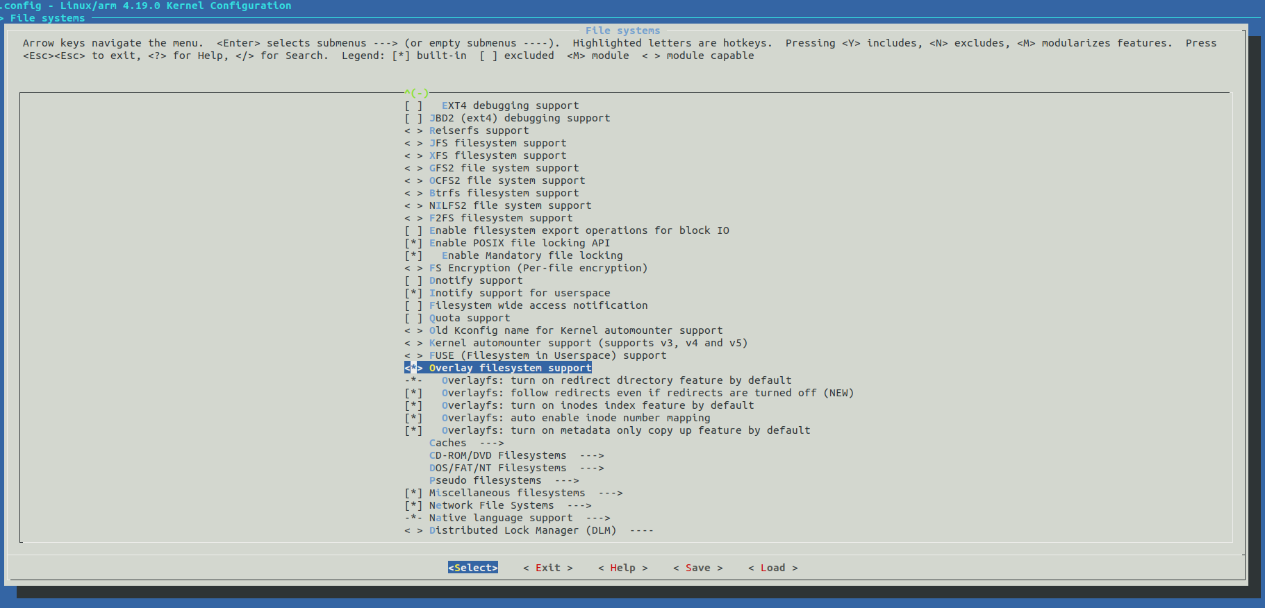
How to compile DTS file in order to generated DTBO
If you have an SDK from yocto, then it is pretty easy. This is how I do. Here, the output is phyDriver.dtbo and the input is phyDriver.dts. Remember, you need to use -@ DTC flag so that it can use the existing symbol from the device tree.
#/opt/poky/2.7.3/sysroots/x86_64-pokysdk-linux/usr/bin/dtc -o dtb -o phyDriver.dtbo -@ ./phyDriver.dts How to load the DTBO file First, create a directory inside the overlays i.e. /sys/kernel/config/device-tree/overlays. Afterwards, copy the contents of the phyDriver.dtbo to the dtbo file there. For e.g., copy the contents of phyDriver.dtbo to the /sys/kernel/config/device-tree/overlays/phyDriver/dtbo. Here is what I am doing here.
root@microzed-zynq7:~# mkdir -p /sys/kernel/config/device-tree/overlays/phyDriver
root@microzed-zynq7:~# cat /home/root/phyDriver.dtbo  > /sys/kernel/config/device-tree/overlays/phyDriver/dtbo
Problems I faced
Here was my first DTS file.
/dts-v1/;
/plugin/;

/ {
fragment@1 {
	__overlay__ {
	#address-cells = <0x1>;
	#size-cells = <0x1>;
	custom_port_phy {
	#address-cells = <1>;
	#size-cells = <0>;
	compatible = "custom,custom-port-phy";
	Dummy_Port_Phy0: dummy_port_phy@0 {
	  			       reg = <0>;
				       speed = <1000>;
				};
				Dummy_Port_Phy1: dummy_port_phy@1 {
					reg = <1>;
					speed = <1000>;
				};
			};
		};
	};
};
When I loaded the DTBO file, I got the following error.
root@microzed-zynq7:~# mkdir -p /sys/kernel/config/device-tree/overlays/phyDriver
root@microzed-zynq7:~# cat /home/root/phyDriver.dtbo  > /sys/kernel/config/device-tree/overlays/phyDriver/dtbo
OF: overlay: find target, node: /fragment@1, no target property
OF: overlay: init_overlay_changeset() failed, ret = -22
create_overlay: Failed to create overlay (err=-22)ss
How did I fix this
This was pretty easy to fix since it was complaining very loudly that I am missing target property. So, I checked a couple of examples and I decided that I need to provide a target property there. Here was my revised DTS file.
/dts-v1/;
/plugin/;

/ {
fragment@0 {
     target = <&amba>;
	__overlay__ {
        #address-cells = <0x1>;
	#size-cells = <0x0>;
	custom_port_phy {
        #address-cells = <1>;
	#size-cells = <0>;
	compatible = "custom,custom-port-phy";
	Dummy_Port_Phy0: dummy_port_phy@0 {
	  			       reg = <0>;
				       speed = <1000>;
				};
				Dummy_Port_Phy1: dummy_port_phy@1 {
					reg = <1>;
					speed = <1000>;
				};
			};
		};
	};
};
Compile the above revised DTS file Afterwards, I again tried compiling the device tree and then tried loading the DTBO. However, the loading still failed with a different error. Here is what I have seen.
root@microzed-zynq7:~# cat /home/root/phyDriver.dtbo  > /sys/kernel/config/device-tree/overlays/phyDriver/dtbo
OF: resolver: no symbols in root of device tree.
OF: resolver: overlay phandle fixup failed: -22
create_overlay: Failed to create overlay (err=-22)
How to fix the above issue and what does it mean? Again the error was loud that there are no symbols. So, I started looking onto more closely on what is meant by symbol. One thing for sure this error has come from target = <&amba>;. So, I thought probably it doesn’t know what is amba? After a lot of search, I found that the problem is that before even I loaded the DTBO, the device tree didn’t have symbols. The DTBO relies on symbol since symbol wasn’t there the DTBO failed. So, the root cause was the DTB file and not DTBO. The solution here is to build the device tree with ‘-@’ DTC flag so that it generates the symbol. Once symbol are there, DTBO won’t compile.
Here is the device tree without symbol.
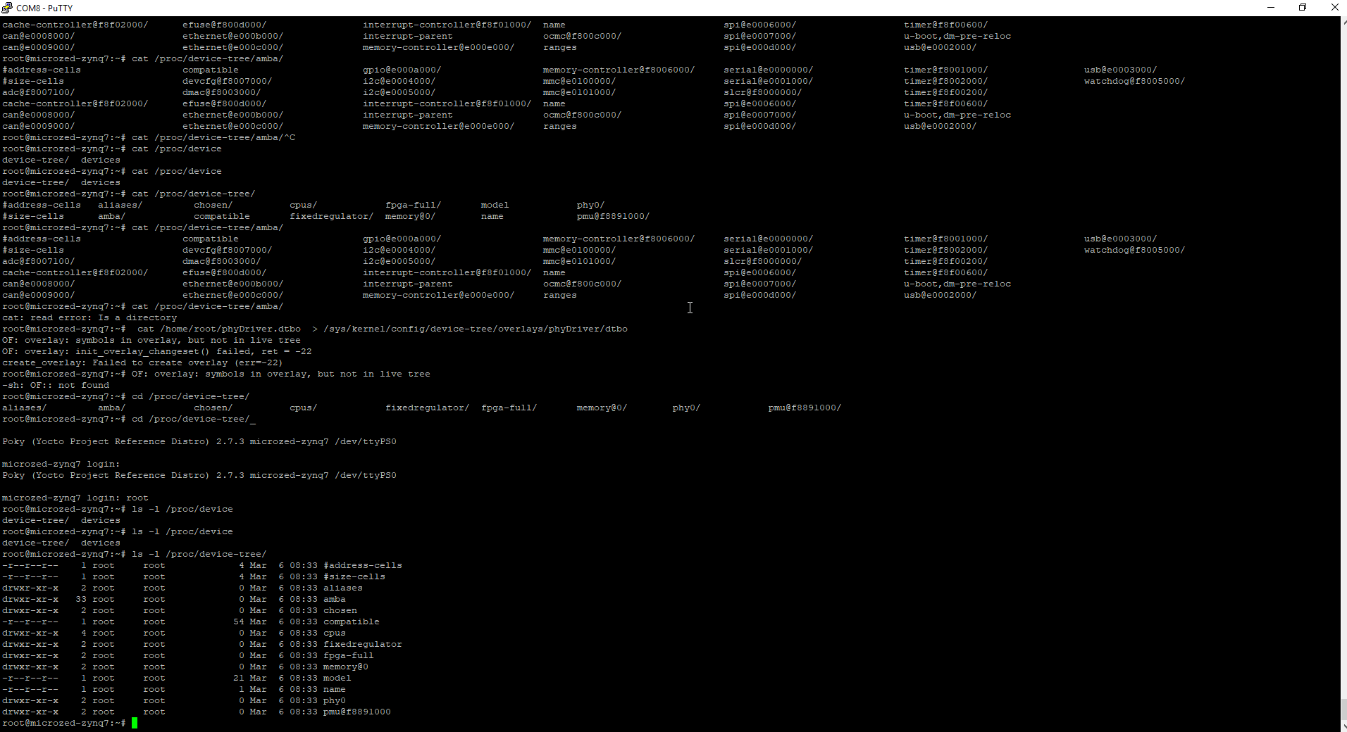
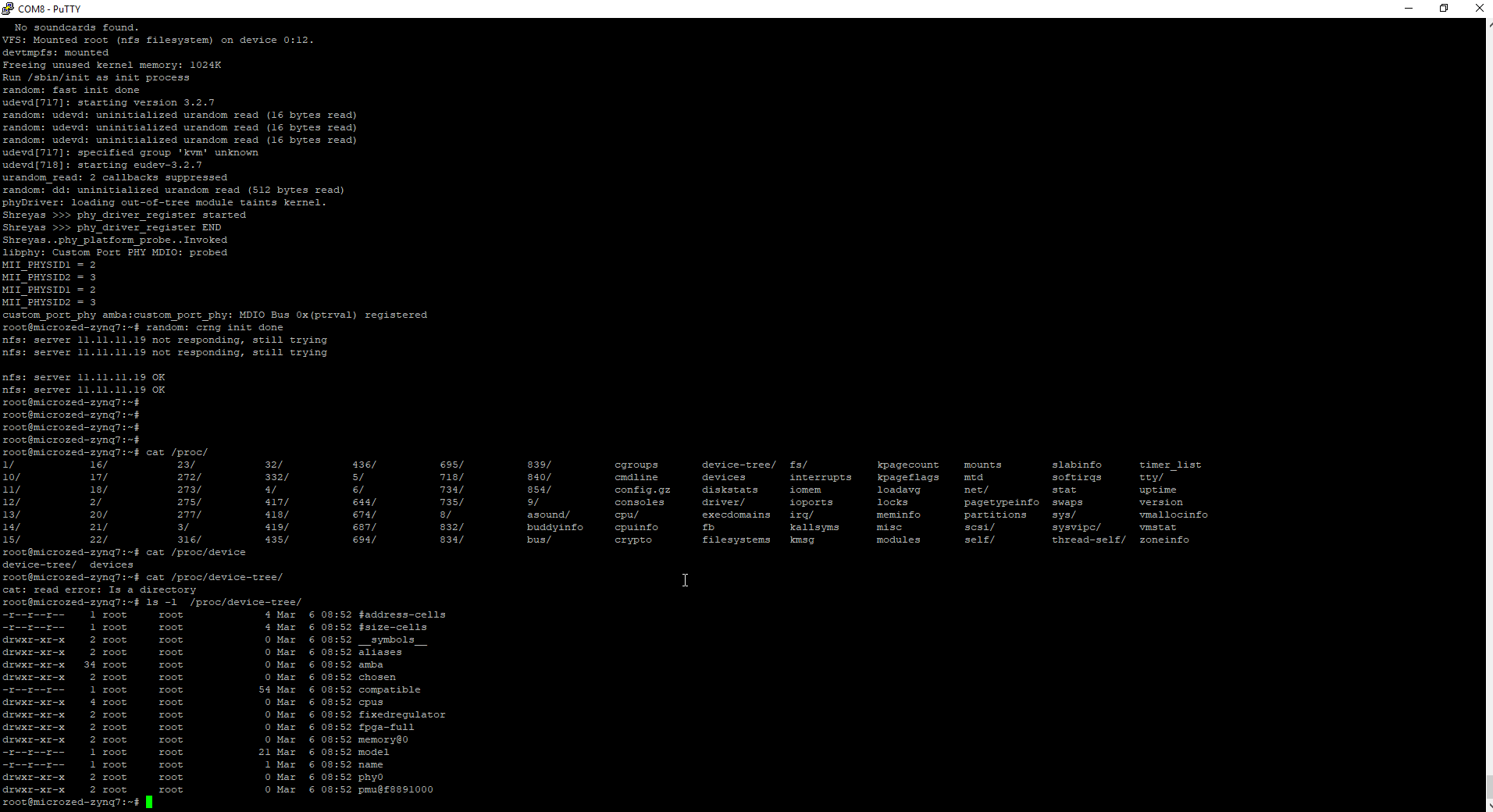
After the fix, you can see that the device tree has got the symbols.
Reverse Engineering to know from where it is reading DTS file to create devicetree.dtb file
shreyas@shreyas-VirtualBox:~/microzed/poky/build(warrior)$bitbake -e core-image-minimal| grep KERNEL_DEVICETREE
# $KERNEL_DEVICETREE
KERNEL_DEVICETREE="zynq-microzed.dtb"
    if d.getVar("KERNEL_DEVICETREE"):
        dtbs = d.getVar("KERNEL_DEVICETREE").split(" ")
since, you know the name of the dtb file i.e. zynq-microzed.dtb, you can search for this string.
shreyas@shreyas-VirtualBox:~/microzed/poky(warrior)$grep -ir zynq-microzed.dtb ./meta-xilinx/
./meta-xilinx/meta-xilinx-bsp/conf/machine/microzed-zynq7.conf:KERNEL_DEVICETREE = "zynq-microzed.dtb"
How to compile Device Tree in Yocto
bitbake virtual/dtb -c compile -f
bitbake virtual/kernel -f -c deploy
How to add device tree flag
In order to generate symbols in the device tree, we need to compile the device tree with the device tree flag - “-@”. You could add this flag in the local.conf file in yocto.
DEVICETREE_FLAGS += "-@"How to compile device tree locally using devshell I have tried this method and it works all the time and is most reliable way.
bitbake -c devshell virtual/kernel
$DTC_FLAGS="-@" make dtbs
$cp ../../../work/microzed_zynq7-poky-linux-gnueabi/linux-xlnx/4.19-xilinx-v2019.1+gitAUTOINC+9811303824-r0/linux-microzed_zynq7-standard-build/arch/arm/boot/dts/zynq-microzed.dtb
$rm -f ../../../work/microzed_zynq7-poky-linux-gnueabi/linux-xlnx/4.19-xilinx-v2019.1+gitAUTOINC+9811303824-r0/linux-microzed_zynq7-standard-build/arch/arm/boot/dts/zynq-microzed.dtb
Now, I loaded the device tree. Afterwards, I loaded the device tree overlay. After loading the device tree overlay, I loaded my phyDriver. This is what I saw.
#insmod phyDriver.ko

phyDriver: loading out-of-tree module taints kernel.
Shreyas >>> phy_driver_register started
Shreyas >>> phy_driver_register END
Shreyas..phy_platform_probe..Invoked
libphy: Custom Port PHY MDIO: probed
MII_PHYSID1 = 2
MII_PHYSID2 = 3
MII_PHYSID1 = 2
MII_PHYSID2 = 3
custom_port_phy amba:custom_port_phy: MDIO Bus 0x04df9772 registered
Device Tree Editor I couldn’t fina any device tree editor other then a plugin in VSCode. Here is what I have used to edit or write device tree.
https://marketplace.visualstudio.com/items?itemName=plorefice.devicetree How to build linux kernel module out of the yocto tree This can be achieved by using yocto SDK. The first step here is to generate the kernel development source headers. This is achieved by appending the following in your yocto local.conf file.
TOOLCHAIN_TARGET_TASK_append = " kernel-devsrc"Now, build the SDK.
bitbake core-image-minimal -c populate_sdkYou might still face a problem like -
./include/uapi/asm-generic/int-ll64.h:12:10: fatal error: asm/bitsperlong.h: No such file or directory
 #include <asm/bitsperlong.h>
This was pretty annoying so I did the following to resolve this issue. I had to go to the SDK folder and had to run scripts and prepare command to fix those issues.
root@shreyas-VirtualBox:/opt/poky/2.7.3/sysroots/cortexa9t2hf-neon-poky-linux-gnueabi/lib/modules/4.19.0-xilinx-v2019.1/build$source /opt/poky/2.7.3/environment-setup-cortexa9t2hf-neon-poky-linux-gnueabi
uild$make scripts
$make prepare
PLL - Phase locked loop This is a part of processor, the PLL lives inside the processor. The PLL job is to give clocks to different peripherals. Also, PLL can divide or multiply the clock to give different clock rates to a different peripherals attached. For e.g. UART baud rate will differ based on the clock rate being given by the PLL. In short, processor gets the clock from oscillator, external or something else. Next, the PLL lives inside the processor. The PLL job is to give different clock rates to different peripherals. The PLL can be configured to give a different clock rate to a particular peripheral. PLL stands for phase locked loop. It is a controlled circuit.
This brings an end to this article. Here is the entire embedded system running.